
The purpose of a wet electrostatic precipitator (WESP) is to remove particulates that are smaller than one micron from a gas stream. One of the common industrial applications is downstream of standard pollution control equipment on power plants or pulp mill facilities. Power plants typically use wet electrostatic precipitators after all other pollution control equipment for polishing. Pellet mill facilities use wet electrostatic precipitators upstream of RTOs to prevent buildup on the RTO media. Particulate removal is achieved by sending process gas through an array of high voltage electrodes and grounded collectors. Particles in the gas are charged and then attracted to the collector surface; clean gas continues up the WESP.
The outlet section of a WESP houses the insulator compartments. Insulator compartments support a high voltage grid which holds the discharge electrodes in place. This arrangement separates the high voltage grid from the grounded section. The introduction of purge air through the insulator compartment reduces dust and moisture buildup on the walls of the compartments. This not only keeps the insulator bushing clean but also maintains a positive air pressure to prevent process gases from entering the compartment.
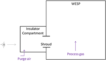
The diagram above shows how the WESP is connected to the insultator compartment with a shroud. Operating the system at minimum purge air flow helps reduce operating cost as less energy will be required to heat up the purge air. The caveat here is that inadequate flow will result in wet process gases swirling into the insulator compartment through the shroud from the WESP. In an attempt to optimize our operating conditions, flow simulation was performed to analyze the flow pattern of purge air through the shroud at varying inlet flow rates.
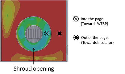
The close-up view of the shroud shown on the bottom was taken facing the insulator compartment with WESP at the back. The green/blue color indicates air flow towards the WESP (into the page), while the red/yellow represents flow towards the insulator (out of the page). This illustrates a positive air flow into the WESP achieved at minimal flow rate. Under this operating condition, energy savings will be maximized while ensuring no swirling of wet process gas into the insulator compartment.
To see how this modeling is applied, download our case study on treating a lead fume using a wet electrostatic precipitator.
