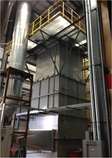
Thermal oxidation of fossil fuels or other sulfur containing material generates sulfur dioxide, SO2. Petroleum refineries, secondary lead smelters, paper and pulp manufacturers, geothermal power generators, waste incinerators, and mineral processors are the primary emitters of SO2.
SO2 contributes to respiratory illness and aggravates existing heart and lung conditions. It contributes to acid rain, damaging vegetation, sensitive ecosystems, and waterways. It is one of the six common criteria pollutants. Criteria pollutants are subject to primary and secondary National Ambient Air Quality Standards (NAAQS) under the federal Clean Air Act. Primary standards prevent adverse effects on human health.
Packed bed absorbers are a common wet scrubber technology for removing SO2. Absorbers use sodium hydroxide (NaOH), often referred to as caustic, or soda ash (Na2CO3) to neutralize SO2. Relative to other air pollution control technologies, packed bed absorbers achieve high removal efficiency, possess a low capital cost, are highly automated, and require minimal maintenance with high reliability.
When absorbed into water, SO2 solubilizes to sulfite (SO3). SO3 requires further oxidation to stabilize in water. If left unoxidized, SO3 increases the chemical oxygen demand of the wastewater and can convert back to SO2 resulting in toxic offgas.
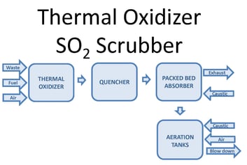
One way to oxidize the wastewater is through forced oxidation. This oxidizes sulfite (SO3) reaction products to sulfate (SO4). Forced oxidation can increase the size, complexity, and operating cost of the system. The PFD image below shows a block diagram of a thermal oxidizer SO2 scrubber with forced oxidation. Waste, fuel, and air combust in a thermal oxidizer. Sulfur compounds in the waste oxidize to SO2. After the thermal oxidizer an evaporative quencher cools the gas to its saturation temperature, typically 180°F or lower. The quencher sprays water into the gas, cooling it. Some of the water evaporates, increasing the gas water content. The gas then enters a packed bed absorber. Packing provides mass transfer to facilitate absorption of SO2 in the gas into the recirculated water. Caustic in the recirculated water reacts with dissolved SO2 by the reaction shown below:
SO2 + 2NaOH -> Na2SO3 + H2O
The reaction occurs at a pH near neutral. Excess water from the quencher and packed bed collects in the scrubber sump.
When the process requires SO3 oxidation or stabilization, aeration is integrated into the system. Caustic and air inject into the sump. Oxygen in the air oxidizes SO3. An aeration diffuser assembly promotes the transfer of oxygen into the water to facilitate the oxidation reaction.
2SO32- (aq) + O2 (g) -> 2SO42- (aq)
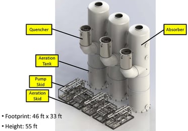
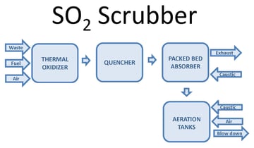 The oxidation reaction is very fast. The limiting step is dissolving oxygen into the water to allow SO3 oxidation to occur. In the case of a low sulfur load, aeration can occur in the sump with little impact on the scrubber size. In the case of a high sulfur load, the scrubber sump requires substantial modification to sufficiently oxidize the SO3. For excessive sulfur loads, oxidation may need to take place in separate oxidation tanks.
It should be noted that forced oxidation is uncommon. Most industrial SO2 packed bed absorbers don’t require forced oxidation. High sulfur load packed bed absorbers are also uncommon. For high sulfur loads, the operating cost of sodium-based reagents make higher capital cost alternatives more palatable. Other options include a limestone spray tower, a dual alkali scrubber, or a lime injection bag house. Each alternative is substantially more capital cost, more complex to operate, and require higher maintenance. When pursuing a forced oxidation SO2 absorber, it’s important to select a vendor capable of properly sizing and designing equipment for both SO2 absorption and SO2 oxidation.
Click on the link below to download SO2 scrubber literature.


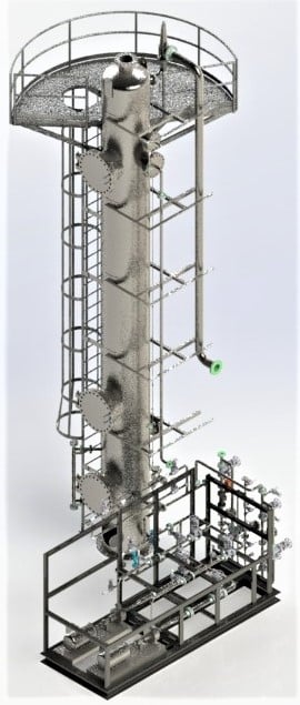

 A catalyst production facility operates a calciner that generates a small stream of hot dirty gas. The exhaust is cleaned using a particulate/SO
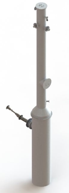
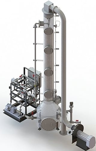 A dual purpose, low flow scrubber is needed for a facility that extracts lithium from geothermal brine. The scrubber treats a chlorine (Cl
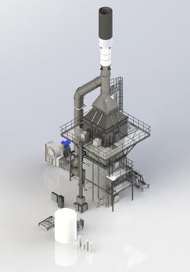
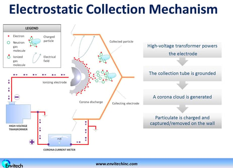 The outlet section is the last section and contains an entrainment separator to collect water drops that were entrained in the gas stream during the collector wash cycle. It also houses a support structure for the high voltage electrodes and wash water spray header.
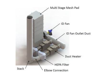 The California Air Resource Board (CARB) is considering new rules in California affecting chrome plating processes for metal finishers. An estimated 100,000 people participate in the chrome plating supply chain. A hundred and fifty chrome plating operations are in California. Eighty to ninety of those are for defense and aerospace applications.
 There are several different waste incinerator source categories controlled by EPA standards under the Clean Air Act (CAA). These include hazardous waste combustors (HWC), sewage sludge incinerators (SSI), municipal solid waste (MSW) incinerators, commercial and industrial solid waste (CISWI) incinerators, and Hospital, Medical, and Infectious Waste Incinerators (HMIWI). Each incinerator type has its own Maximum Achievable Control Technology (MACT) standard which establishes technology based limits for emitted HAPs. MACT standards are part of the National Emission Standards for

 The customer selected
 The adjacent figure illustrates WESP’s primary use. The graph shows removal efficiency on the vertical axis and particle size on the horizontal axis. The red curve shows typical WESP performance. The dotted blue curve shows typical Venturi scrubber performance. A comparison shows that a Venturi scrubber is highly effective at removing particles greater than 1 micron in size. However, performance drops off rapidly for particles below 1 micron. WESP performance is relatively immune to particle size and maintains high performance for particles below 1 micron. This capability is derived from the use of electrical forces for particle removal compared to a Venturi scrubber which uses mechanical forces. WESP’s are generally higher capital cost than Venturi scrubbers but lower operating cost. They are used in cases where performance cannot be achieved with a Venturi scrubber or other, lower cost control device.
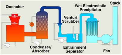 WESPs are often integrated with other control technologies and used as a polishing device at the end of a process. This is shown in the adjacent illustration for a typical waste incinerator. Perhaps the most important aspect to understand about WESP technology is the relationship between performance, size, and cost. Higher performance requires more collection area, larger footprint, and more cost. This is different than other control technologies like a Venturi scrubber or packed bed scrubber. For these devices, size and cost is primarily determined by the gas flow rate while operating cost is determined by performance. Size and cost for a WESP on the other hand is determined not only by gas flow rate but also removal efficiency. It is therefore important to have a good understanding of the range of inlet particulate concentrations and outlet emission limits. Specifying performance of 90%, 95%, or 99% removal will make a substantial difference on size and cost.