Air Pollution Control Innovations

CFD in Air Pollution Control Systems

Posted by Andy Olds on Tue, Oct 27, 2009 @ 06:00 AM

By Mike Simon
Director of Simulation Products, Digital Dimensions

Understanding how simple design changes affect the airflow inside of Envitech's products is critical in designing efficient industrial gas cleaning systems.  Engineers who design this equipment need to analyze and understand the behavior of the components if they want to improve performance.  Computational Fluid Dynamics (CFD) is a good tool for studying the effects of different design changes on these systems.  CFD provides a way to save time and money in obtaining the necessary information, and assists engineers in designing better quality air pollution control systems.    The use of CFD makes it possible to minimize the use of physical prototypes and find serious flaws much earlier in the design process. 

SolidWorks is the 3D CAD system used by Envitech to design their industrial gas cleaning systems.  SolidWorks has a number of complementary features to its mechanical CAD system including CFD capabilities that are fully integrated within the main CAD interface.  SolidWorks Flow Simulation is the name of the CFD program inside of SolidWorks that allows engineers to take their 3D CAD models and perform virtual prototyping on their designs without having to fabricate any parts.  To perform a simulation, the following steps are needed:

  • 1. Create solid model in the SolidWorks CAD system
  • 2. Specify the working fluid ( air was used in this case)
  • 3. Specify the flow rate at the duct inlet
  • 4. Specify the outlet opening of the duct
  • 5. Specify the pressure drop or resistance properties of the filter material (properties taken from filter manufacturer specifications)
  • 6. Run the simulation inside of the SolidWorks interface

Flow Simulation


Envitech's products were particularly challenging since Envitech's products utilized very thin fins and packing materials within a large ducting area.  Thin fins are used to direct the airflow and also to collect water from entering the system.  SolidWorks Flow Simulation was able to capture the geometry of these thin fins and create a corresponding CFD model for the simulations.  Packing material is used to help distribute airflow and trap particulates from being released into the environment.  The porous media feature inside of SolidWorks Flow Simulation was used to simulate the packing material and create the additional resistance to the airflow.  After performing the simulations, the Envitech engineers had the ability see the effectiveness of the scrubber fins in directing the airflow and to understand the pressure drops caused by the packing material.  The simulations helped the Envitech engineers validate their designs and gave them additional insight into how to improve future product performance.

For additional information on SolidWorks CAD or SolidWorks Flow Simulation software, go to http://www.ddicad.com/ or contact Mike Simon, Director of Simulation Products, at msimon@ddicad.com.

For a case study on the impact of CFD analysis, click on the link below.

Download  Case Study

Topics: Venturi scrubbers, Scrubbers, wet electrostatic precipitators, Guests

Pharmaceutical Scrubber

Posted by Andy Olds on Tue, Oct 13, 2009 @ 01:50 PM

pharmaceutical scrubberAs the EPA continues to tighten the emissions belt, I am seeing new industries with air emissions issues. One such industry is pharmaceuticals, who are now more commonly regulated for acid gases on post-combustion devices.

Pharmaceutical air emissions are typically a result of an organic fume from a solvent. The fume, containing vaporized solvent, is captured either within a fume hood or central ventilation system. When regulated, the most effective way of removing a fume is to combust it in a regenerative thermal oxidizer (RTO) or some other combustion device.

The combustion of a solvent such as methyl chloride in an RTO leaves three compounds: carbon dioxide, water vapor, and hydrochloric acid. The last of the three - hydrochloric acid - is often treated as an emission and if so must be removed from the outlet exhaust.

Pharmaceutical Scrubber 

The most best method for removing hydrochloric acid from a gas is the use of a pharmaceutical scrubber. A scrubber offers extremely high efficiencies (greater than 99%, or as required) at a low pressure drop. Recirculating neutralized water across a packed tower, the capital and operating cost of a scrubber is minimal. Further, the effluent from a HCl scrubber contains only sodium chloride - table salt - and can easily be disposed of through a wastewater sewer with little to no further treatment. Using FRP for the scrubber provides a low cost building material highly resistant to acid attack.

Hydrochloric Acid Corrosion

The removal of hydrochloric acid from a combustion exhaust does offer one particular difficulty over other common acid gases, of which designers and operators in the pharmaceutical industry need to be wary. Hydrochloric acid and neutralized chlorides are very aggressive towards most metals, especially so at elevated temperatures typically seen on the outlet of a combustion process. Since the HCl is contained in the exhaust of a combustion process, the inlet gas temperature to the scrubber is high. In turn, the recirculation water temperature is also high, usually well above 100F. Standard metallic materials such as stainless steel will quickly corrode in this environment.

In the past, I have used both AL6XN and hastelloy for metallic materials in HCl scrubber systems. Common metallic items in a pharmaceutical scrubber include the quencher, instrumentation, and downstream devices.  AL6XN is a duplex material that provides very good corrosion resistance to around 1000F. It also has about an order of magnitude greater chloride pitting resistance than stainless steel at neutral pH, and over two magnitudes resistance at low pH.  AL6XN is ideal for quenchers on the exhaust of an RTO, where the outlet temperature is usually around 500F. Hastelloy is more expensive, but it offers heat resistance to 2500F as well as a further order of magnitude resistance to chlorides over AL6XN.

Hydrochloric Acid Mist

The other issue provided by hydrochloric acid in a gas stream is the formation of hydrochloric acid mist, which I have previously touched upon in my acid gas dewpoint post.

Hydrochloric acid mist usually requires a high efficiency mesh pad for removal of any HCl aerosols that may form in the scrubber.  A mesh pad is more expensive than a standard wave form mist eliminator, and is also much more prone to particulate plugging.  If hydrochloric acid is in your gas stream, make sure you consider a mesh pad and beware of particulate!

If you would like to learn more about corrosive acid gas scrubbers, download the free case study below.

Download  Case Study


Topics: Scrubbers, Acid Gas, quenchers

Wet Scrubbers for meeting the new HMIWI MACT Standard

Posted by Andy Bartocci on Wed, Oct 07, 2009 @ 01:26 PM

In my previous blog post I outlined new rules that were promulgated on September 15th, 2009 for the hospital, medical, and infectious waste incinerator (HMIWI) maximum achievable control technology (MACT) standard.  Wet scrubbers are used on many of the existing medical and hazardous waste incinerators to meet this MACT standard.  The unfortunate news is that new control strategies are required to meet the more stringent standards.

The new emission limits present challenges for both existing and new systems.  These challenges  relate primarily to the follwet scrubberowing pollutants.

      • Particulate
      • Lead, Pd
      • Cadmium, Cd

The particulate limits for new systems are reduced from 0.015 to 0.008 gr/dscf.  This is a 50% reduction.  The lead (Pd) emission limits are reduced from 1.2 to 0.036 mg/dscm for existing systems and from 0.07 to 0.00069 mg/dscm for new systems.  The cadmium (Cd) limits are reduced from 0.16 to 0.0092 mg/dscm for existing systems and from 0.04 to 0.00013 mg/dscm for new systems.  The new Pd and Cd limits for both existing and new systems are nearly a 100% reduction.

There are 4 keys to meeting these more stringent standards with wet scrubber systems.

  • Add-on particulate polishing package
  • Sub-cooling
  • Venturi Scrubber
  • Mist elimination

Add-on particulate polishing package

The new emission limits will exceed the design capability of most of the existing wet scrubber systems today.  This will require an add-on polishing 
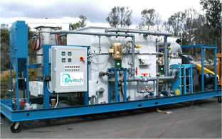
control to meet the more stringent standards.  Envitech has had success achieving higher removal efficiencies by integrating an add-on particulate polishing package (PPP) into incinerator wet scrubber systems.  The PPP is comprised of a skid mounted package that provides slight reheat of the gas temperature to slightly above saturation in combination with a filter system.  The reheat eliminates the potential for condensation build-up in the filters.

This strategy has been used for both commercial and industrial waste incinerator scrubbers (CISWI) and low level radioactive waste incinerator scrubbers. Removal efficiencies of > 99.8% was achieved for both Pd and Cd at the outlet of the Venturi scrubber which already has a very low particulate load < 0.015 gr/dscf.  This has proven to be a cost effective strategy to meet the new standards.

Sub-Cooling - Sub-cooling the gas in a medical or hazardous waste incinerator scrubber provides several advantages.  It makes use of condensation effects to enhance particulate control in a downstream Venturi scrubber. The water vapor in the gas condenses onto the particulate and grows them in size.  A particulate that is 0.3 microns will grow to about 0.7 microns after condensing the water vapor. This makes it easier to collect in the downstream Venturi.  A second advantage of sub-cooling is condensing metals (i.e. Pd and Cd) as much as possible from a gas phase to a particulate. This allows them to be collected downstream in the scrubber.  The final advantage is steam plume suppression. Removing the water vapor eliminates a steam plume under most meteorological conditions.  This reduces the visibility of the system in the surrounding community.

Venturi Scrubber - The particulate capture efficiency of a wet scrubber system is determined by the pressure drop across the Venturi scrubber. Higher removal requires higher pressure drop.  Sub-cooling discussed above enhances the Venturi performance by growing the size of particulate.  Often times this reduces the power consumption by half for most medical and hazardous waste incinerator wet scrubbers.  The new HMIWI standards, however, exceed the practical capability of a Venturi scrubber. This can be overcome with an add-on particulate polishing package discussed previously.  It is recommended to optimize the Venturi scrubber performance to minimize the load on the PPP. This reduces the annual operating expense by increasing the life of the filter elements.

Entrainment Separator - An entrainment separator or mist eliminator is used after the Venturi scrubber to knock out water droplets in the gas stream.   Any water droplets that escape the mist eliminator will contain pollutants which can cause a stack test failure.  A horizontal, chevron style mist eliminator is commonly used in incinerator wet scrubber systems.   Effective mist elimination is important for the add-on particulate polishing package discussed previously.  Water droplets can lead to fouling of the add-on control.

As facilities get their arms around the new rules for the HMIWI MACT, they will need to consider all of the above items for complying with the new standard using a wet scrubber system.

Please read our paper on meeting the new HMIWI MACT standards by clicking the link below.

Download Free White Paper

Topics: particulate control, Venturi scrubbers, Scrubbers

Venturi Scrubbers for EPA HMIWI MACT Standard

Posted by Andy Bartocci on Thu, Sep 24, 2009 @ 02:54 PM

On September 15th, 2009, proposed revisions to the New Source Performance Standards (NSPS) and Emission guidelines (EGs) for the HMIWI standards became final. These regulations, originally promulgated in 1997, were established under Section 129 of the Clean air Act (CAA), and serve as the maximum achievable control technology (MACT) standards for hospital, medical, and infectious waste incinerators.Venturi Scrubber

The proposed revisions included both a five year review and a response to a court-ordered Remand.  Many industries have been following these new revisions closely, including the American Forest & Paper Association (AF&PA), the Portland Cement Association (PCA), the Council of Industrial Boiler Owners (CIBO), the National Brick Research Center (NBRC), and the National Lime Association (NLA), among others.  The methodology used by the EPA to formulate these revisions may eventually be applied to the industries of these groups. 

There are a number of objections to the new rules which are viewed by some in industry as unachievable.  One of these objections relates to the establishment of floors for the best-performing units for each of the regulated pollutants individually. This has been considered by some as a MACT-on-MACT approach which may result in the need for a combination of control technologies. 

Below is a summary comparison of the previous emission limits (1997) and the new emission limits (2009) in response to the Remand for new and existing HMIWI units for large, medium and small incinerators.  Many hazardous and medical waste incinerator scrubbers meet the previous emission limits (1997) with a Venturi scrubber system.  However, the new standards for both existing and new HMIWI units are significantly more stringent with respect to particulate, Pd, and Cd.  The new standards, would be met with the same basic technology, however, add-on controls would be needed as a polishing step in most circumstances.  In a future blog post, I'll discuss add-on control strategies that can be used to meet these new requirements.

LARGE INCINERATORS, > 500 LB/HR


    1997 2009 1997 2009
Pollutant Units Existing Existing New New
Particulates, EPA Method 5 gr/dscf 0.015 0.011 0.015 0.0080
HCl, EPA Method 26 ppmv, or 100 6.6 15 5.1
  % reduction 93% - 99% -
SO2 ppmv 55 9 55 1.6
Pb EPA Method 29 mg/dscm, or 1.2 0.036 0.07 0.00069
  % reduction 70% - 98% -
Cd, EPA Method 29 mg/dscm, or 0.16 0.0092 0.04 0.00013
  % reduction 65% - 90% -
Dioxins/furans, EPA Method 23 Total (ng/dscm) 125 9.3 25 9.3
  TEQ (ng/dscm) 2.3 0.054 0.6 0.035

MEDIUM INCINERATORS > 200 TO < 500 LB/HR

    1997 2009 1997 2009
Pollutant Units Existing Existing New New
Particulates, EPA Method 5 gr/dscf 0.03 0.020 0.015 0.0095
HCl, EPA Method 26 ppmv, or 100 7.7 15 7.7
  % reduction 93% - 99% -
SO2 ppmv 55 4.2 55 1.4
Pb EPA Method 29 mg/dscm, or 1.2 0.018 0.07 0.018
  % reduction 70% - 98% -
Cd, EPA Method 29 mg/dscm, or 0.16 0.013 0.04 0.0098
  % reduction 65% - 90% -
Dioxins/furans, EPA Method 23 Total (ng/dscm) 125 0.85 25 0.47
  TEQ (ng/dscm) 2.3 0.020 0.6 0.014

SMALL INCINERATORS, < 200 LB/HR

    1997 2009 1997 2009
Pollutant Units Existing Existing New New
Particulates, EPA Method 5 gr/dscf 0.05 0.029 0.03 0.029
HCl, EPA Method 26 ppmv, or 100 44 15 15
  % reduction 93% - 99% -
SO2 ppmv 55 4.2 55 1.4
Pb EPA Method 29 mg/dscm, or 1.2 0.31 1.2 0.31
  % reduction 70% - 70% -
Cd, EPA Method 29 mg/dscm, or 0.16 0.017 0.16 0.017
  % reduction 65% - 65% -
Dioxins/furans, EPA Method 23 Total (ng/dscm) 125 16 125 16
  TEQ (ng/dscm) 2.3 0.013 2.3 0.0130


All emission limits are measured at 7% oxygen.

For more information about this rule, please download our white paper via the link below.

Download Free Paper

Topics: Venturi scrubbers, Scrubbers, MACT Standards

Acid Gas Dewpoint

Posted by Andy Olds on Mon, Aug 31, 2009 @ 09:00 AM

acid gas scrubberAcid gases can be found in the exhaust of a large number of combustion processes.  As a gas, the acid compounds usually are not particularly corrosive and are relatively easy to remove.  However, when the temperature of the gas drops below the acid gas dewpoint, an acid mist can form.  The acid mist can turn into a fine aerosol or it can condense on a cold surface.  Acid mist poses a number of design problems, due to the small size of the mist particles and the corrosivity of the liquid form of the acid.

Aerosol Formation

Aerosol formation occurs when the bulk temperature of the gas drops below the acid dewpoint of the gas.  Much like the formation of fog, the acid gas condenses into tiny liquid droplets.  The size of these droplets can vary widely depending on the acid, the amount of condensation nuclei present in the gas, and degree of supersaturation.

The most common problem that occurs with acid aerosol formation is the inability to capture the aerosol.  Many acid gas exhaust treatment systems utilize a packed bed scrubber to remove the acid.  Packed bed scrubbers are extremely efficient at removing acid in the gas, but unfortunately are ineffective at removing acid aerosol.

The solution to removing acidic aerosol mist is to use a high efficiency entrainment separator or Venturi scrubber, which can effectively capture particles to 1-micron or 0.5-micron, respectively.  If the acidic aerosol mist is primarily sub-micron in nature, a wet electrostatic precipitator also provides a useful solution.

Wall Condensation

Wall condensation occurs when a cold surface is in contact with a hot gas.  If the wall is cooler than the acid dewpoint, acid can condense onto the surface of the wall.  There are several dangers with wall condensation.

First, the material selection for an acid is dependent on its form.  Many acids are not corrosive as a gas, but are very corrosive as acids.  Engineers selecting materials under the assumption that the acid remains a gas often choose materials that are not compatible with the acid in its liquid form.

Second, when condensed, the acid is much more concentrated than it is in the bulk medium.  Instead of selecting a material for a gas containing 10 ppm of SO3 gas, the engineer now has to worry about a nearly pure sulfuric acid droplet.

Finally, the acid can condense in non-ideal locations, leading to pooling and further corrosion concerns.

The solution to preventing the effects of wall condensation is to insulate walls to prevent cold surfaces and select materials for the concentrated, liquid form of the acid in locations where wall condensation is unavoidable.

Acid Dew Point

All gases have a dew point that is dependent on the temperature, pressure, and concentration of the acid in the gas.  This article provides acid gas dewpoint equations for a number of acids.  Below are the formulae for a few of the more common acids in exhaust gases.

Tdp = Dewpoint Temperature, K

Pw = Partial Pressure of water, mmHg

Pa = Partial Pressure of acid, mmHg

Hydrochloric acid (HCl)

1000/Tdp = 3.7368 - 0.1591 * ln (Pw) - 0.0326 ln (Pa) + 0.00269 * ln (Pa) * ln (Pw)

Sulfur Dioxide (SO2)

1000/Tdp = 3.9526 - 0.1863 * ln (Pw) + 0.000867 ln (Pa) - 0.000913 * ln (Pa) * ln (Pw)

Sulfuric Acid (H2SO4)

1000/Tdp = 2.276 - 0.0294 * ln (Pw) - 0.0858 ln (Pa) + 0.0062 * ln (Pa) * ln (Pw)


Click on the button below to down load an Envitech packed bed absorber cut sheet for acid gas removal.

Download Cut Sheet

Packed bed absorber cut sheet

Photo Credit: tinyfroglet

Topics: Venturi scrubbers, Scrubbers, wet electrostatic precipitators, Acid Gas

Instrumentation

Posted by Andy Olds on Thu, Aug 27, 2009 @ 02:25 PM

air pollution control instrumentationOne of the most difficult value engineering challenges I encounter is the selection of instrumentation.  Instrumentation within air pollution control systems may be subject to high salinity, high halide concentrations, pH swings, extreme temperatures, extreme ambient conditions, intrinsically safe environments, and abrasive particulate, just to name a few.  Selecting the proper instrumentation for each environment is a chore and can dramatically effect the cost.  It is a topic that both end-users and integrators should attempt to resolve before a system is built.

Extreme temperatures

Most know of the obvious differences between outside environments as opposed to inside environments.  Rain, snow, and sun all batter instruments outside; equipment inside rarely see any of the three.  Extreme heat though is not the exclusive domain of outside environments - I am currently working on a project where inside temperatures can reach 140F.  For that project, I have moved all of the temperature sensitive transmitters inside an air conditioned control cabinet to meet the temperature requirements of the analyzer.  When dealing with extreme temperatures, it is best to find ways to reduce the effect.  For extreme cold environments, use insulation or heat tracing.  For the extreme heat, look at moving sensitive electrical equipment into a temperature controlled environment.  Remember, plan for the extremes!

Be a copycat

A lot of the projects that I see are retrofits - the addition of new air pollution control equipment on existing processes or equipment.  In these cases, it is usually best to select instrumentation that is already working well within the plant.  First, copying instrumentation removes most doubts of instrument failures.  Second, operators have a familiarity with the instrumentation, and are more apt to use the instrumentation properly.  Finally, copying instrumentation reduces the number of spares that a plant needs to keep available, thus reducing the net cost of the instrument.  Whether you are buying the equipment for a customer, or buying equipment with prepackaged instrumentation, always find out what instrumentation is already working! 

Preventive Maintenance

Even after selecting the right equipment, there is still the need to properly maintain the equipment.  Acid gas scrubbers almost always require a pH probe for dosing basic reagents; those pH probes require regular calibration and often have lifetimes of six months.  A probe off by 1.5 pH units can cause a drop in acid gas removal efficiency from 99% to 75% - a significant problem if your stack tester is visiting! Conductivity sensors and hardness analyzer and ion selective electrodes also require regular maintenance.

For instruments that do require calibration, it is important to use bypasses to allow for calibration during operation.  A bypass loop with an instrument hold function allows an operator to carefully calibrate the instrument while the system continues to operate in a safe fashion.

Recommendations

Above all else, work with the end-user to identify instrumentation requirements.  A customer running a 24/7 operation has dramatically different requirements for instrumentation than one that is on a single shift operation or batch process.  Operators should be thought of as well.  Are the instruments accessible?  Can operators view indicators?

Remember, selecting the right instrumentation minimizes downtime; downtime that may cost you ten times the price of the instrument.

Topics: Venturi scrubbers, Scrubbers, wet electrostatic precipitators

Ammonia in Syngas

Posted by Andy Olds on Fri, Aug 14, 2009 @ 06:00 AM

Ammonia SyngasThe primary products of synthetic gas (syngas) production from biomass are hydrogen gas, carbon monoxide, and methane.  Unfortunately, those are not the only compounds formed.  Other compounds form depending on the elemental chemistry of the biomass.  One of the more common byproducts is ammonia, released from organically-bound nitrogen.

Why ammonia rather than NOx

Organically-bound nitrogen converts to ammonia, rather than NOx, in a gasifier.   Gasifiers are typically oxygen-starved environments.  Conversion of organic nitrogen to NOx requires oxygen.  Without oxygen, combustion thermodynamics favor the production ammonia.  In fact, ultra-rich combustion environments produce reduced compounds, like ammonia, rather than oxidized compounds.

Why it is still NOx

The main goal in the production of syngas is to eventually burn it!  Ammonia left in the syngas WILL convert to NOx in a rich combustion environment, like an internal combustion engine or a syngas-fired boiler.  NOx is a heavily controlled environmental pollutant and it is important to minimize its production.

How do I remove it

Fortunately, ammonia is significantly easier to remove than NOx.  Ammonia can be removed with an ammonia scrubber using water and sulfuric acid.  Ammonia reacts with the sulfuric acid to form ammonium sulfate.  Provided any particulate is removed upstream, an ammonia scrubber can produce a very high concentration of liquid ammonium sulfate that has commercial value as a fertilizer.  Since sulfuric acid is relatively cheap, the operating costs of an ammonia scrubber are minimal. 

Ammonia gas can also be formed using a scrubber/stripper approach, first removing the ammonia in an ammonia scrubber, and then liberating the ammonia as a gas in an ammonia stripper.

Envitech's experience with ammonia scrubbing spreads into other industries.  Please read our white paper on the reduction of ammonia emissions for a sludge dryer.

White Paper

Photo Credit: ajturner

Topics: Scrubbers, biomass, syngas

Acid Gas Scrubbers and Calcium: Solutions

Posted by Andy Olds on Wed, Jul 22, 2009 @ 04:11 PM

acid gas scrubberCalcium scale occurs everywhere.  The photo on the right shows calcium carbonate scale lining the rock formations in Lake Mead, just above Hoover Dam.  The calcium from this photo deposited as a result of dissolution of calcium in upstream limestone rock formations along the Colorado River, followed by evaporation and reprecipitation in Lake Mead.  In a roundabout way, this is the same method that calcium scale forms in a scrubber.  Calcium enters via the feedwater (Colorado River), concentrates due to evaporation (the hot Nevada sun), and forms a precipitate as the calcium concentration exceeds the solubility limit (lime deposits).


In my previous post, I detailed how to determine if calcium is a problem in your acid gas scrubber.  Here, I will detail several methods for avoiding calcium scale and, when it arises, cleaning calcium scale.

Avoiding Scaling

The best way to tackle scaling is to avoid scaling. There are three basic methods to avoiding scale:

1.  Remove the calcium

The easiest way to avoid calcium is to remove the calcium!  First, try to select a feedwater that does not contain calcium.  Condensates are often an excellent source of calcium-free feed water.  If calcium-free water sources are not available, investigate the cost associated with a softener.  Companies like Culligan offer a wide range of softeners.  Water softening is a competitive market; there are often local suppliers that can offer low cost solutions.

2. Adjust the chemistry

There are several tricks that can be employed to permit higher concentrations of calcium in your scrubber water without leading to scale formation.  For situations where calcium carbonate is the primary scale, you can decrease the pH of the scrubber.  Acid gas removal efficiency decreases when operating at a lower pH, but the drop in efficiency can be overcome by increasing the packing height (and thus the number of transfer units).  Decreasing the pH decreases the LSI index of the water; LSI indices less than 0 are non-scaling.

Companies like Nalco also sell anti-scalants that reduce the activity of the calcium ion in solution, thus eliminating the potential for calcium scale.  Anti-scalants are usually much more expensive than acid treatment, but also permit operation at a higher pH which is more conducive to acid gas scrubbing.

3.  Increase the blow down

In my previous post, I documented how the calcium concentration was tied to the blow down flow rate.  One of the easiest and most practical solutions therefore is to increase the blow down flow rate.  Increasing the blow down flow rate reduces the concentration of both the calcium and associate scaling anion (CO3, SO4, F) in the scrubber recirculation water.  While increasing the blow down flow rate will add cost by increasing the feed water flow rate (to make up water removed in the blow down) as well as increasing sewer and other wastewater charges, it is often preferable as a quick fix solution for reducing scaling.

Coping with Scaling

In many ways, scaling is inevitable.  A process upset, an exhausted bed, or a blocked blow down valve - these things happen.  How do you remove the scale?

Calcium carbonate is the most common scale.  It is also amongst the easiest to clean.  Lowering the pH is the most aggressive way to dissolve the scale, though running at any LSI << 0 will tend to dissolve the calcium carbonate.

Calcium sulfate is another common scale, especially in an SO2 scrubber.  The best method for removing calcium sulfate is using hot, low pH water to remove the scale.  Calcium sulfate, like calcium carbonate, will dissolve.  Chelants such as EDTA are also helpful for this form of scale.

Calcium fluoride is the worst scale to remove, since it has such a low solubility.  Physical methods work best for calcium fluoride, as dissolving calcium fluoride is difficult.  Some chelants such as EDTA are available on the market for removing calcium fluoride, but are not likely to be as effective as with other forms of scale.

To learn more about Envitech's acid gas scrubbers, please download our packed bed cut sheet.

Download Cut Sheet

Note: Photo of Lake Mead by Tim Pearce

Topics: Scrubbers, Acid Gas

Acid Gas Scrubbers and Calcium: The Problem

Posted by Andy Olds on Thu, Jul 16, 2009 @ 03:04 PM

Acid ScrubberAcid gas scrubbers are commonly used for the removal of acid gases, such as sulfur dioxide, hydrochloric acid, chlorine, hydrofluoric acid, and nitrogen dioxide.  These scrubbers typically use a basic reagent; often sodium hydroxide, soda ash, or lime to keep the scrubber liquor at neutral to high pH.

Operation at a high pH can lead to unexpected problems with water chemistry.  Calcium carbonate, calcium sulfate, and calcium fluoride all can cause scale within the scrubber.  Scale can reduce the effective pipe diameters, coat packing, block nozzles, foul instrumentation.  In the worst extremes, calcium scale can shut down the scrubber and in turn shut down the upstream process equipment.

How does one avoid such hazards?  In the first of this two part series, I will go through the five steps for determining if calcium scale is a threat to your acid scrubber.

Step 1: Determine the calcium concentration

Calcium primarily infiltrates an acid scrubber through two sources: water makeup and chemical addition.  Water makeup is typically from a municipal or well source.  The calcium concentration can usually be found in municipal water reports.  Well water can be tested cheaply at an outside laboratory for calcium.

Calcium content for sodium hydroxide and soda ash is a bit more difficult to determine, but can be specified in the procurement of the chemicals.  Using the chemical consumption rate and the blow down flow rate, the amount of calcium left in the scrubber water can be calculated.  Lime actually contains calcium, and should be avoided where calcium scale is possible.

Step 2: Determine the scaling anion concentrations

The three most common calcium scaling anions are carbonate, sulfate, and fluoride. Carbonate primarily enters the system through fresh water, though in acid gases with high carbon dioxide content carbonate can also absorb into the water.  Sulfates enter through fresh water, but due to the high solubility of calcium sulfate, rarely cause problems due to makeup water sulfate.  Instead, sulfates are a byproduct of the neutralization of SO2.  SO2 neutralizes to HSO3 and SO3 in water, and can convert to SO4 depending on the residence time, pH, temperature, and oxygen content of the acid gas.

Step 3: Calculate the buildup of calcium and the scaling anions.

Determining the concentration of ions in the scrubber requires two steps.

1.  Sum all of the mass flow rates (mg/min) of the ion into the scrubber water, including makeup water, chemical, and absorption from the gas.

2.  Divide the mass flow rates by the blow down flow rate (L/min) to give a concentration (mg/L).

Step 4: Calculate the LSI index

The most common form of calcium scale is calcium carbonate.  Calcium carbonate is formed by the interaction of calcium with carbonate alkalinity.  Carbonate alkalinity is often present in fresh water; carbon dioxide can also dissolve in water to create carbonates.

The LSI index offers the best method for determining calcium carbonate scaling; Edstrom provides a wonderful explanation at their website.

Step 5: Calculate the sulfate and fluoride solubilities

The final step is to determine the sulfate and fluoride solubilities. 

Calcium sulfate is relatively soluble, but calcium sulfate scale can still occur in SO2 scrubbers. Scale forms for calcium sulfate if the solubility product exceeds 4.93x10^-5.  The solubility product for calcium sulfate is equal to the concentration of calcium (mol/L) times the concentration of sulfate (mol/L).  The calcium concentration can be converted from mg/L to mol/L by dividing by 40,000.  The sulfate concentration can be converted from mg/L to mol/L by dividing by 96,000.

Calcium fluoride is the opposite of calcium sulfate; it is extremely insoluble.  Scale forms for calcium fluoride if the solubility product exceeds 3.45x10^-11.  The solubility product for calcium fluoride is equal to the concentration of calcium (mol/L) times the square of the concentration of fluoride (mol/L).  The calcium concentration can be converted from mg/L to mol/L by dividing by 40,000.  The fluoride concentration can be converted from mg/L to mol/L by dividing by 96,000.

Click on the icon below to download a white paper about other challenges associated with acid gas scrubbers.

Download Paper

Topics: Scrubbers, Acid Gas